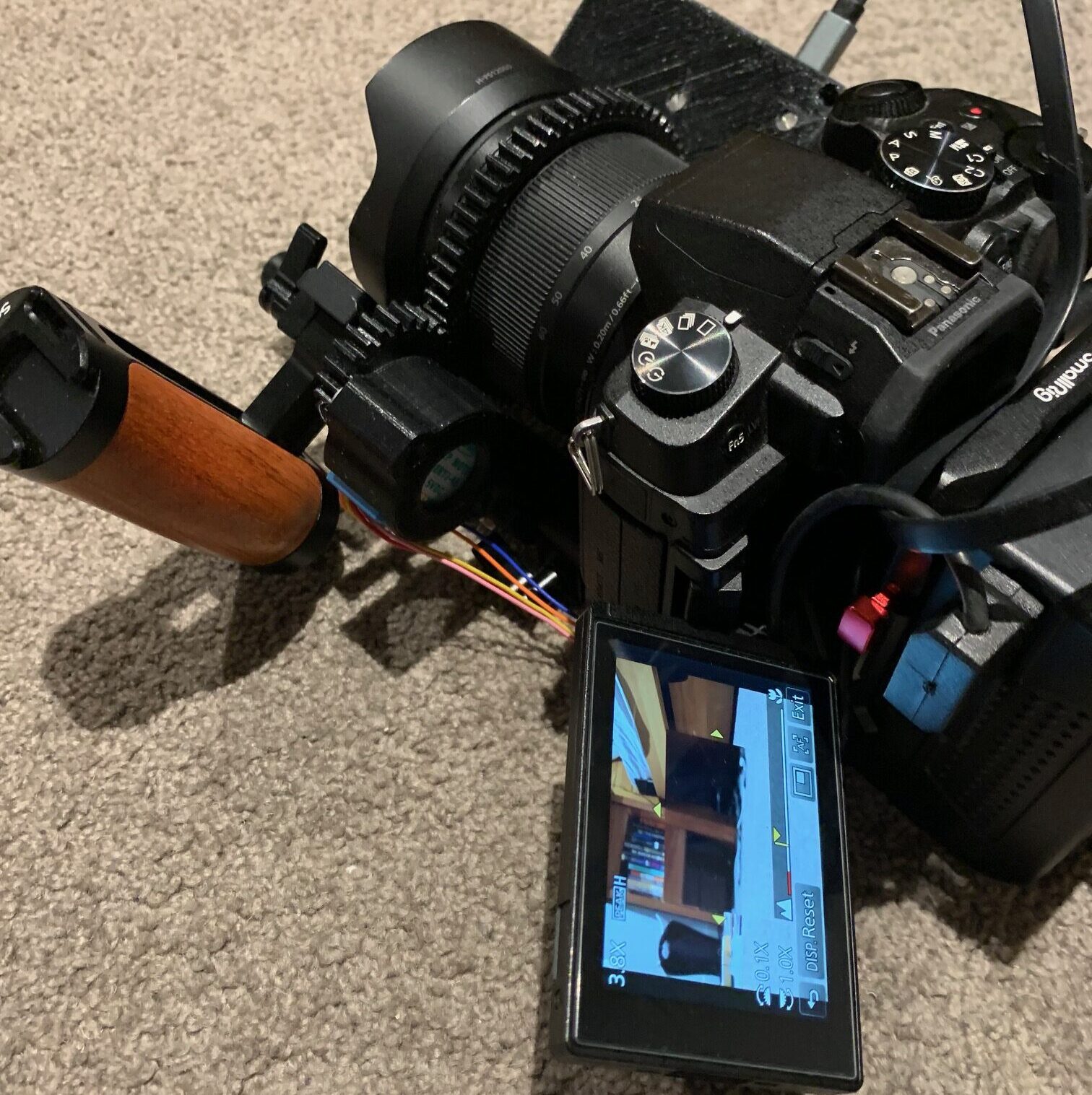
Due to coming down with Covid in mid 2022, I had some extra time on my hands so decided I’d build myself an electric follow focus to control zoom or focus on my camera for my upcoming media project. Previously I had just
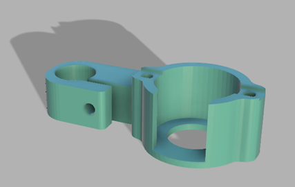
Motor Housing Design
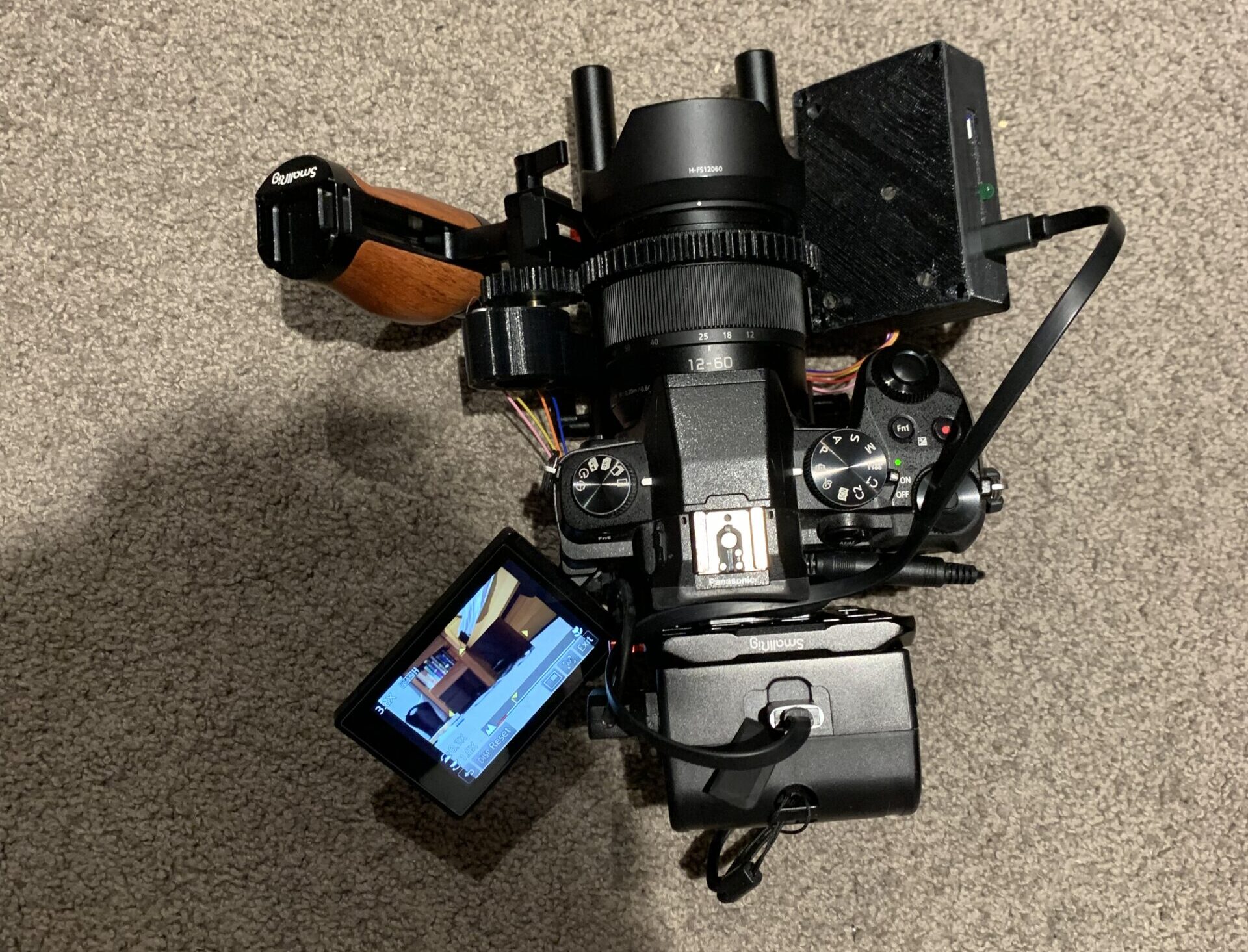
I began by designing the motor housing which would attach to the 15mm tubes used for mounting to a camera rig. I took a picture of the motor and its mounting holes from the top down to and then using some callipers took its exact measurements. This allowed me to then model around in knowing that the actual motor would fit correctly and be secure. I then combined this mount with an attachment for the tube and this gave me the part which would physically move the rings.
The Code
From here I began working on the code and control side of the project. I wanted to future proof the design by allowing remote connection to the device which could allow for remote control of the camera if it was hard to reach. Originally, I planned to use an RF transmitter and receiver however they had issues so instead I switched to a Wi-Fi based communications system.
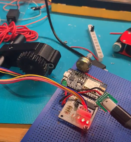
This system works by creating a webserver on the host board to handle incoming signals, then it creates a local wifi network acting as a router which the other board can then connect to and communicate with. This also allows for other devices such as a phone or laptop to connect. The manual control is done through an analogue potentiometer which is then converted to a digital signal and used to control the movement of the motor. Finally there is a green light which indicates when a signal is being received.
Circuit Design
To plan out my circuit before creating it I used a piece of software called Fritzing. This allowed me to plan out the whole circuit with the different components and draw the traces. This was important as it prevented possible issues to do with components not fitting or making the wrong cuts or traces.
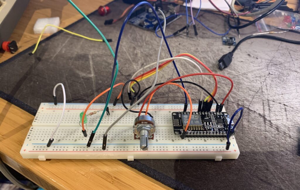
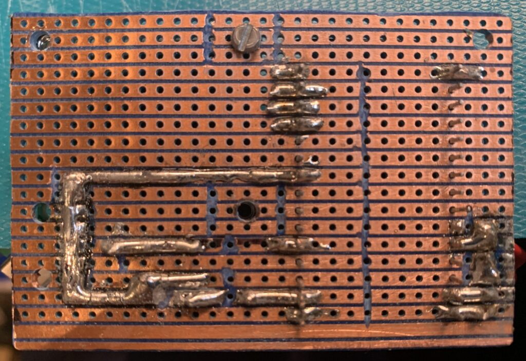
Board Assembly
Thanks to my planning the board assembly was relatively easy and straightforward. I began by drilling the mounting holes into the breadboard using a Dremel. Then I used some painters tape to hold the components in place whilst I soldered them to the board. Then using the soldering iron I made the traces needed and attached any wires. Finally I used the Dremel to cut the disconnects in the copper traces to prevent any short circuits.
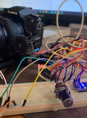
Case Design and Final Assembly
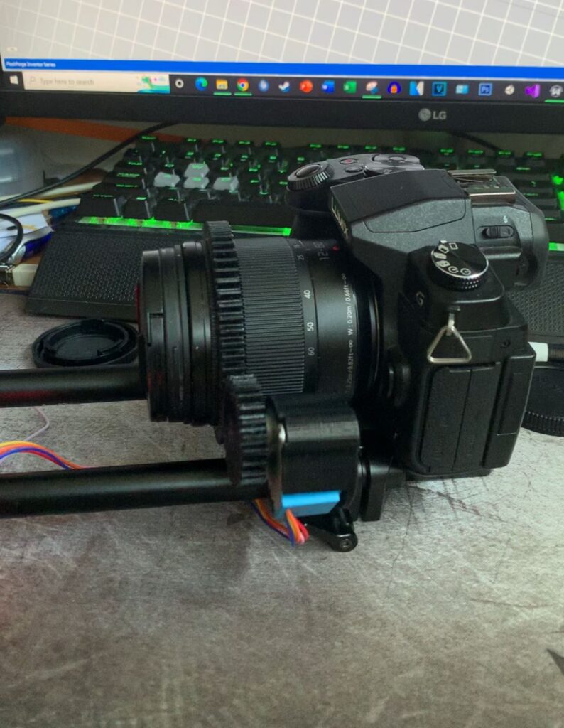
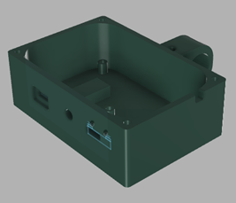
To create the case for the main board, similar to the motor housing, I took a picture of the board and measured the distances between the mounting holes are added stand offs for it to mount to. I then also added slots in where the ports and LED were and designed a special place where the USB C board could slide in and be hot glued in place. This ended up taking two 3D prints to make, as the first one due to how it was printed, had a weak mounting point and could not securely attach to the rods.
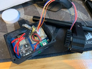
In order to mount the board I sanded down the corners to make it fit and bolted it in place. Before then attaching the potentiometer to the top cover and bolting it on top and completing the construction. Then I installed the board and screwed it into the standoffs in the case. The USB C port was then slid into place and both it and the LED was hot glued for added stability. Once this was done I mounted the potentiometer to the lid and screwed it in place.